Tuesday, October 25, 2011

the task of tasks has begun


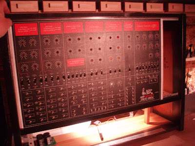
so ive begun to wire up the ody and its associated components.. i had to really familiarize myself with its circuitry a bit better and see if what i laid out and had in mind was going to actually work.. so far id say 100% ..its a total fucking miracle actually. i was able to get done VCO 1 and its patch points, switches and pcb connections. the breakaway headers offer much better eas of use to remove and fit/test hings and also though, they double the wiring time it takes to each section. but for what they allow its very worth it for me. here are some pics of the prelimary session on the ody..

yes. that is a HUGE repro/printout of the PCBS! its fanstatic to have as a reference or as for art! right now its great since i can see component values, traces and component numbers/designations. its ideal.

the face plate and pcbs can be removed seperately and in any fashion/combination really. i wanted to be able to access the inside from either the rear or the front. so , so far this design has worked out really good.

Tuesday, October 18, 2011

quick studio panarama

heres a quick peek inside....

Sunday, August 28, 2011

more of the current...


heres the poly 6 as i recieved it. its pretty beat. no power connection . its been cut off and stripped (frightening) . so with that guy we're pretty much starting at zero. i spliced a quick poer cord on.. it powered up. no smoke and alot of ill behaviour though. upon a quick initial inspection i found : battery is not exploded (good) . several corrosive spots on pcbs from previous soda spills (bad) general oxidation of traces (bad) alot of free floating objects ( 4 pennies, 3 screws) inside (that could cause shorts it in contact with the WRONG things.. (VERY BAD) . so lets say that i'll start with a serious bath for all those pcbs in some iso alcohol and high pressure air to blow them dry. then deoxit all the connectors. remove the battery and maybe put in a coin cell if i can get it running. not to mention installing an IEC socket for the power cord. what a fuckin mess. i have a feeling this may be a "ill buy it for parts" kinda repair job for me. it might not make it back from the grave. it depends on how much the client is willing to spend on her. shes time intensive for sure. mine was.
if you notice the serious grime on it from the pic of the single wipe of tissue with iso on it. wow. mad grime. then you can se the clean spot that was made when i swiped it.. nasty shit. so we'll see if i can get it running then maybe made a little nicer looking after her hearts beating..:)

current status buffer : full!


so the benches are seriously full: no vacancy. im knee deep into the ARP ody redo, which is about 3 projects in itself. ( the ody and case, the distro section and then the mfos minisynth under it) both the MFOS and the ody are augmented with an extra MFOS envelope as well.. so yeah.. then i have another sequencer peripheral row expander unit that has 2 more rows of cv with coarse and fine tunes and each has the controll line mod i did. then i got my friend Karl's octave kitten to fix and open on the main bench.. add to that now the 909's rim trigger issue to solve (workaround and maintenence in progress) . i also have a poly 6 which is fairly fucked to repair for a client in detroit.
and an emax II rack to assemble for a friend in florida.

so yeah theres alot onthe benches now. to say the least.

heres some pics of the current things...

Saturday, June 25, 2011

THE ODESSEY OF THE ODESSEY


so i got an arp ody whiteface from a friend. sliders were real fucked. since i really didnt want to pay 400 usd for a set or replacements i decided to harness the boards and remove all sliders and switches .. cut off the keys and make it pached out to point (1/8 jacks) .. alot of work. you betcha it is.
its pretty much redoing all but electronics. im also adding a new ps and another env and 4 amped and attenuated distros to it. along with adding a jacked out patched out MFOS minisynth in the cab below it to use in conjunction with it. how long and dark can i make that tunnel??? reeeeeeal long.

heres what it looks like now and stauts picks

Wednesday, March 23, 2011

tah dah!


fianally after lots of work, probing, testing, metering, soldering , tapping, cutting and cursing: its done! hell yeah.

all tested and installed into its home. heres some pics and video of the sequencer driving a sequential circuts pro-one. using the A channel gate and slide feature while B channel cv does the p1 filter.

so worth it. this things quite fun. when in random mode it could easily be a backdrop for Space 1999, doctor who, or buck rodgers, or perhaps even "mother" from aliens" flashing lights as if to say 'computing, computing, computing. "

its one of a kind that im glad to have taken the time and effort to have built. the digital line inversion make the machine extremely crazy. i had it doing alternat lines by switching halfs of the sequence and using 8 per side. it was ridiculous kinda.

Sunday, March 13, 2011

DRUM ROLL PLEASE....

well heres the vid of everything running with the 4 bit control line modification...
its almost hard to know what happening....

only the battle has been won...


well after some serious diagnosis, goose chasing and alot of pin pointed tested.. its running. 100%
ALL SYSTEMS ARE A GO!

itseems there was a bad solder connection on the CV A channel that was casuing it to have a output of -1.3 v.. weird. but i resoldered and reheated things and BAM! there it was.

so second issue that was left . the gate B line. it was not reaching full hysteresis threshold for the 40106 portion of the circuit to flip and invert. so everythin after that wasnt happening. it took a long while to track down the culprit. there was somethin in the gates' led cathode bus that was grounding when it shouldne have been. another issue i had was that the B rows leds were VERY bright even with the same value resitor in place to ground as the A line.. this was a shining example of where i should have started to look. im supposing that there was something .. aerrant piece of wire/solder/metal .. SOMETHING that was connecting that bus to ground. since when i was testing and isolating things.. i discoed the bus line from ground and the leds still worked!?!?!?! W T F ? so obviously somewhere else something was touching to ground. after a while and another weirdness, it went to normal. ! hot damn! but im not sure why the other weirdness happened.. the CV A's tl084 snapped and POPPED! just like that. it totally shit itself.. nothing touched it, connected with it or anything... so i replaced that and began a full test .

so now every module works as it was designed to.
including the prototype of the SLIDE>. its mad sweet.

now all thats left is the module for the xternal clock trigger comparator-buffer and the wiring of the trigger outs to 2 DB25's for the gate hold module. then that guy gets tucked into his case and ever so gently put into place.... man i cant wait!
here are some pics and videos.

Monday, March 7, 2011

more pics.


power connections, 4 bit line switchers, db 15's for the swithcers and .01" headers for every connection to and from anything moveable or modifiable. (what a chore!) the reason for all the cable length is that the entire aluminum frame that all the pcbs are on is swing open able from the right side. so as to have access to the pots and switches for repairs. so the lengths have to reach when opened fully. i think id figure out a different design if i did this again. .. its not the easiest thing to deal with...


leviathan pics

here are some pics of the machine.. im still diagnosing some off the issues with circuits misbehaving.. but all leds run in correct fashion. (5 rows of 16!!!)
ill upload some videos of the display soon. it utilizes 3 of the 4 bitch switch modification that ive discovered.... it at times looks like its broke, but is just running quite as it should..:)


Sunday, February 27, 2011

houston, all systems are go...

i tested all the sytems this weekend on the DRAX 2.5. thumbs up! i still ahve to check all cvs and gate voltages and such bu as for what the leds should be doing, we're on point.

heres a pile of pics...

Saturday, February 26, 2011

dawning of the levaithan..

so it was a super nice interlude doing the diy synth from doepfer.. but it only honed me up for the second round on the sequencer. after my incredibly botched test from a couple weeks ago, i decided that since there were far too many mistakes and shortcuts taken on that main board.. i decided to get another from MFOS. so i repopulated it very carefully, and with forthought of any mods and kluges neccessary. so the other day i got to test the heart of it and the see it run..:) YES! i tested the A channel of gate and cv. all was good. the gate can use the 4 bit inversion mod or run normal while the cv line runs moded. i made a little switcher tester set-up for the bench and then hooked p and connected the b line and that gate as well. DING another winner! then last was the slide and its led generator.. OHH SNAP! 3 for 3. all the connections have .10 headers to connect them with corresponding pots, buses, jacks, buffers etc, so it took quite a while to do the connectors and to get all the wiring coded, and discernably labeled.

so far its all good. i havent been able to see every channel running yet though since i dont have 3 sets of mod switchers on the bench test set up. so i would run one at a time to test the lines and connections. really the last thing will be testing the actual functions to make sure the cvs aer correct and that the gates are correct . i also have to wire the slide bus to the corresponding normal and portamento outs. then its trimming the pot shaft lengths with the dremel, wiring the connectors for the clock and rest links to the previos sequencers, finishing the rear panel connections for external 4 bit outs and power etc, and attaching the opening door/case for the entire enclosure, then last but not least putting on all the knobs and the rosewood trim strips. once all thats donr.. the very very last thing will be to make the 3- 12 conductore cables that go to the 4bit mod line inverters. then its install time. about fuckin time. whew....

Sunday, January 30, 2011

beginning to take a very nice form...


i had about 2 hours today to work on the MINIMONO some more.. i got all holes machined to the right tolerances and then set the face overlay in play and did the double bond adhesive. i use 3M SUPER77 . its fantastic on metal and plastic and cleans up real nice with naptha. so it went on like a DREAM! everything was exactly where it should have been. nice change. :) anyway, in that 2 hours i also got about a 3rd of the harware on and set in place.. the pacthfield jacks are always a pain to me.. i just hate doing them.. but its all good. and i wanted to see just a couple (literally) knobs on it before i had to leave. i also got the case assembled, but still have to fabricate the inside mountin rails and the face trim/spacers for the faceplate. i also have to make the armature that supports the tiny pcb for this synth. which is an incredibly minor task compared to the sequencers..

oh... i also cleaned out the holes for the hardware with the dremel and a conical shaped rotary edged blade. it is fantastic for the job and if needed can final trim/grind any faceplate material that is hindering correct placement of the hardware. i heeeeeeeaaaaaaaart the dremel.

the case is maple ply for the top and bottom panels and the sides are solid sepelea. they are actaully book leafed from l to r and the same iece was sliced down the middle long ways... im attentive to detail on the cases lets say.

anywa heres some pics of the the process and current status until i next building session.

one year... wow.


so its been almost a year since i started this DIY adventure into the land of sequencers and CMOS.. ive been working on the last one for a long while now.. i tested the heart of it last weekend. it was a horrible failure. i had soooo many things wrong and mis-connected. i couldnt believe what i was seeing. i also couldnt get the cd40193 to advance the count of the cd4514 multiplexor chip... in essense the sequencer wouldnt move from its initial step (0) . so there were soooo many bets hedged and gamed on the system., i thought i could just go ahead and wire everything and it would work. what a foolish idea. so.. i had to desolder the main control board and all connex to the panels and triggers/gates. no fun. actually it was demoralizing. but after a bit i looked at it as a step in the right direction. so i went back to zero: i ordered another control board and started at 0. im re populating it all very carefully and am going to hedge only 1 bet: the 4 bit control line hack/inversion. thats the only varaible i want to introduce new into the equation here. i also want to check EVERY switch and connection. i had all the dpdt switches for the gates and leds wired incorrectly.. so i had to undo that mess as well. anyway. i made a switch tester/simulator so i can check the hack mod without having it down in the studio itself and do it on the bench.

so as this project was moving slowly (now) foreward.. i had also gotten as present from my wife a DOEPFER DIY synth for xmas.. its a one of everything complete analog synth pcb thats assemebled and working. all you do is connect the power supply to it and wire all the pots and such and fabricate the case/enclosure to your liking. its incredibly patachable and has nice features. state varaible filter and nice mod points. so i was sending the ARP oddysey faceplate to the printers so i picked up the pace and added the doepfer to it as well. i named it the MINIMONO. since it has one everything. and its an incredibly small pcb. and had a good ring to it. so i sent that , the arp and a redone faceplate for a control voltage mod dual row unit out to the printers here in town. gotem back with the machining mechanicals. fan fuckin tastic. i have the control voltage (DSVC is its name) on and am beginning to clean out the holes and getting ready for harware install. the MINIMONO is all drilled. all parts have arrived (pots/ switches/headers) minus 2 switches for the env timand the lfo mode.. i have also made the case for it and have that just about ready. it sepelea endcaps with just 1/2 super finished painted black ply between. looks pretty nice and classy old school style. no 90's bad typefaces or anything. class. the MINIMONO and ODY will match design wise. both use the classic ARP styling from the last version of the ODY. i like that . i used black and orange with white letters and boarders. looks stlylish and scientific without being corny or cold. GENEVA was the typface that is almost 99% identical to the ARP stuff. love it. anyway.. heres pics of all the stuff.