Friday, December 31, 2010

gate hold module fabrication/wiring


so heres the super cool switches all set in their repsective spots.. i used angle aluminum from home depot to fabricate the housings/faceplates. i made a template for the mounting screws and then figured out the correct spacings from front/side to side for a 19" rach unit with enclosure. so after i got the measurments i laid out all the holes and punched them (to minimize drill bit drift) and then used a fence on the press bed of the drill press to even minimize variance further. worked pretty well.

i then used a dremel to cut the u shaped holes into the aluminum for switches. i didnt cut the horizontal of the u but rather scored it about half way thru. this allows then to snap the alunimum off in a very precise sharp corner with no ugly over cut marks. i then cleaned the u out with a nice file. very efficient. what wasnt efficient and time consuming was tapping the holes (32 in each row ) x2 rows. for the switches. that took some time and delicacy. (4/40 taps dont like to be twisted or torques to hard. theyll say no and snap)

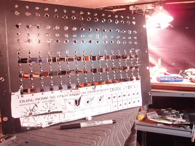
i used 3 pieces of angle stock to make each row. (oddly enough this is just a 1/16th over the actual size of one U rack measurments) i have this sitting in ait own area so its not directly touching any other rack gear so its no issue... the bottom is just face plate surface and will have the step numbers and info on it. the second is the switch row itself and the 3rd is a 3/4 size piece that will house a bi-colour led (red-green) for staus and scroll/count/step indication. so because of the nature of the mechanical switch you can see to parameters at once. - the hold faetures all together via the yellow mechanical flip, and the current step AND status of that step via the dual color led. so its not too bad.

im re-using an old set of rack ears from an s700 that has been canniballized for another project.. the rear panel for this module will have several db -25 connectors on the back the interfacn/connections to the main sequencer unit. so its all about figuring out now exactly where in the circiut this fucker needs to go...

one biiiiiiig step closer. id say about a month to 2 month it will be testable...:)

Sunday, December 19, 2010

trudging on...

as ivve now spent almost a year doing this never ending sequencer project.. i reach a point where ive actaully been able to see the end.. this last sequencer is so encompassing to create, with so many interconnections. switches and just complexity that its daunting at times. today WASNT one. all cv channels, gate channels, and the slide channel are all now manufactured and connected. all digital line buffers are in and awaiting connection to the main switchers. the gate hold module is about 40 % done. ive uploaded pics of the way ime going to mount the super duper sweet dpdt push buttn latch switches im going to use for it. i found them for a buck a piece from a surplus supply place. they have a machanical status indication inside the button (which allows mw to see a series of gate holds together to know where they start and stop) i count ask for a better switch. they are THE SHIT! and they are double sided as well which really makes the assembly free-er. so these will be used to hold the gates and slur them between steps. (so envelpoes will tie together and open up like a 303 or funky slurs/legato portamento on the minimoog). a very nice little feature that really isnt too terrible amounts of work really.
its all relative.

well heres the pics.

Tuesday, November 9, 2010

ideas as well

ive also found an imterestimg cmos ic. : the cd 4066 quad switch. basicly it 4 switches integrated into one small 14 pin dip ic. you ask how this may be useful? i ll explain.. say you have a row of triggers with physical switches. you have to drill holes for everyone and wire everyone and have faceplate realeastate for each one. thats all well and cool, but depending on how much money u want to spend.. can be costly and time consuming depending on style of switch.. so ive been thinking of this chip for a drum programmer unit. basicly a large trigger sequencer with a ton of rows for triggering drums and envs or whatever. say 4-8 rows depending. so i can have one row of 16 step switches (like the 808-909) and then selelct between the instrument rows for their use. the only issue im trying to solve is one of power to that row after selection is done..

the chip uses and the vdd volatge as the on status for the switch input and the vss voltage (or lack of) for the off. basicly system power and ground. mine would be +12 an ground in this case. i guess i can just switch the power from another source to "hold" the stauts of each switch after i remove the row from the programmer circuit. like a "lock" switch. another issue is that upon powering down all sequences will be lost. but it would enable me to put all of this into say 3 or 4 rack spaces then for 8 rows of gates and triggers. one row of programmer switches (reeeeeal nice ones) and then a 4-8 x 16 grid of leds that correspond to each rows triggering status and one row of counter "current step" leds. just an idea....

also this would involve me going one more step into all of this stuff and etching my own boards. it would only be wise to do this for such a large amount of ic wiring and repeating circuits. and size as well. im working on how to make each row independant lengths and modes as well. (bi directional, reverse, random etc) it would be a seriously ridiculous analog drum programmer unit, that would be super original.

Monday, November 8, 2010

leviathan apraoches


so ive sort of take everything from the first sequencer on here and added all of it to the new one thats about 85% done. additional features : gate hold per sequencer to slur-tie your gates together for envelope holds. selectable per-step portamento (aka "slide" ) like on the tb-303/csq-600/sh-101 sequencers. and last nbut not least 3 sets of digital line inversions for cv channel A, B and Slides! ill have some new pics inthe next couple days.. its been quite a consuming wiring task along with simply figuring out how it needs to be done for all this to happen. im sure they'll be lots of bugs to work out . i never plan on it working right off the bat:) heres a pic of the control line wiring that needs to be done to make this happen.

the other image is the truth tables for cd4067 multi-de multiplexer ic. it is the translation of the 4 bit digital line and how its affected by the inversion of its pulse .. and what that means in reality to the sequencer running. basicly it does nested looping!!!! so it makes really sick variations of your pattern. 16 of them! when used in the "bi derectional" and "reset" modes, this does even weirder and cooler things. i havent been able to count the permutations yet.lets just say theres alot.

Tuesday, July 20, 2010

still

...

more

more

inverted

more video. for real now...

walking through the mirror...

ok. so i went from theoretical to reality. i built the inversion switches and module and installed it into the original sequencer (which had plenty or room in it) and tested it.. FAN*F__KING* TASTIC!

its unreal what i does. it deos exactly what the table suggested , but combined with the step length and reset and bi directional modes on the sequencer .. its craaaaaaazy. you can make the last parts of the sequence loop. have it run n complete reverse (not bi-directional) and have it it do all the nested looping in reverse and within a desired length. its ridiculous. ive only ever seen one seuqncer that will do this.. the RENEE for modular stuff. it makes a linear sequencer. non-lilnear. LOOOOOVE IT> it adds so many new variations to an allready cool sequence.


so heres where reality gets super warped. this inversion hack can be done for any module seperately within that system.. so if i have 2 channels of cv , they can have seperate inversions for each one with no real efort really other than breadboarding one 40106 hex inverter chip. (after the main buffer/inverter is made..)

so i fabricated a set of 4 inversion controls that occupy the very bottom of the new cabinet i made. one will be for this sequencer... i may do the drax version on only the one channel. or maybe one for each.. depends on my mood. since that has 2 channels of cv gate on it. or i may leave that one be since its allready a serious frankenstein creation with haphazard wiring and precarious engineering...

heres some footage of what the inversion hack does.. its driving the sequential circuts pro-one with just a single oscillator for reference.


Wednesday, July 7, 2010

holy inversion batman!


ok.. there are 4 digital control pulse lines that come from the main clocking chip on the mfos sequencer board. they control what step is selected on the multiplexer -demultiplexer chip (cd4067) that selects what pot/sequencer channel is playing and what order. .. so ive been making amping buffer for these signals using a cd40106 hex inverter (2 for each amp up. one gets inverted the other gets re-inverted to normal) but amped to 12 volt for larger spans of wire and multiple submodules.. so if you tap that amp/buffer half way through (the inverted) and the look at the truth table ((((((MATH??????????))))))))) for the 4067.. i sat downa figured out exactly how all that numeric giberish translates to the sequencer order and playback.

HOLY SHIT.

TOTAL MUTATION AND THATS ONLY THE HALF OF IT.

needless to say im adding this into the new one. damn straight.

Tuesday, July 6, 2010

drax phase 2 : rewire.


so i had the choice of ether rewiring the main pots or leaving them as is.. i decided to go for the money and rewire those shits to be right.. so they should go to the hinge side of the rear panel to meet up with breakaway headers that then go to the main cv channels. hopefully the extra work will be justified when i have trouble shoot this bitch. and i know i will for damn sure. theres too many unknowns withthe design right now. the poramento circuit is the only proto of it. :) like scotty rebuil;ding the enterprise.. "i wouldnt bet the farmon it captain..well scotty we dont hava choice do we. im counting on you mr scott." so anyway 2 pics are of the re wire and use of the 16 conductor ribbon, if you do anything that has wiring simular USE THIS SHIT! its fantastic. all electronics has it for very very reasonable prices. and it it well worth the price for the amount of clutter and rats nests it avoids. it tames the wild wires.
the next one after the rewire is the slide mux/de-mux chip that basicly selects between the portamento circuit and the normal circuit. this if it works should be dope. and its and incredibly simple thing. hopefully. i may be speaking too soon...after that is GATE chan B its basicly the same as the main gate section on the digital board except its seperate. and it has to tie to 2 diodes on the main board (d28-29) this adds another channel of gate to the machine. handy for many many things. envs, lfos. drums, retriggering anything. or using it as a second sequence with channel b cv.
after that is the 40106 hex inverter led buffer. it basicly buffers up the leds pulses so as to chain them and add another row of leds to whatever they come from. i like leds... so i need 2 of these guys for on here.

Sunday, July 4, 2010

drax phase 2 continued continued

one more vid..

PAHSE 2 continued..


more pics for the hinge and such...an a vid or 2.

DRAX 2 : phase 2 begins


i have all the main work related components in the face now and all are wired.. minus connex to the board they have to go to. so the next step was to get a hinged back frame to hang all the modules and sub modules on. and start on their arrangement (important). the arrangement depends on what needs to be connected to what and WHERE. the biggest concern was that the 2 boards for the 2 rows of cvs are near and shortest.. since they were allready wired. i had planned on doing things don the center originally but now i see that was mistake .. so all wires should be run down to the right side (from back) and then over to the boards... i can either rewire all the pots whick wouldnt be THAT bad or leave then as is.. i may opt to re wire since ive tried to be logical and plan ahead so far... so the pics are of the back pre frame and post frame.. also theyll be a little video giving a panarama and a demo of the hinge.. simple but effective. now its finish the propagation of the boards and maybe rty to find breakaway headers for the connections. that would be incredibly helpful in the long run.

Thursday, June 24, 2010


drax and poly 6 part 2...


me in front of the drax unit.. its a daunting wall of shit right now.. i work on her piece by piece and hopefully it will all go fairly smooth.. i have a general idea of how it should go so. the pic of the aluminum is the armiture that holds all the boards and sub boards for the unit. this goes over top of the pots and switches in the faceplate. and sits about 1.5 inches or so away in parallel. i have to make this hinge so i can then access the pots and such when and if there will be repairs/adaptations and issues. so then the rear enclosure has a hinge and then the main board assembly will have a hinge as well. just seems like wise plan..the overlay DSVC is the extra 2 row expander module im make ing for this as well.. it extremely simple compared to the drax.. i didnt have the overlay printed i did it on the injet at home.. and seemed it and then sealed it with mylar from the art sore on both sides (3m super 77 spray adhesive wont ruin the clear overlays!!!) the next pic is the actual face plate of the DSVC on the drill press.. i work onthat as time allows as well. i make a simple black and white print out of it with all registration marks for all holes and then rubber cement that to the faceplate and puch drill from there. it gets things like 95% where they should be... ith minimal filing afterwards. so if you want to do it .. try it it that way! the last pic is the cr-8000 switches takes apart for cleaning and such.. they are super delicate and basicly what happens is the carbon comes off the top of the plunger and wont make contact to complete the circiut. so you clean it with a qtip and deoxit d5 and then shave a soft lead pencil for the lead shavings. chop it real fine and then apply it and rub it into the tiny foam pads on the plunger.. it works awesomely and pretty much indefinetely.

drax 2 continued...


well ive done some more wiring and remembered to take some pics this time. i also took some pics of the poly installed into its new home and the cr8000 switches in their undone state. theres a neat pic as well of an upcomming project...:)

Sunday, June 20, 2010

drax-2 002 taking shape


so ive been starting to wire and install all the pots and switches and do some of the preliminary wiring.. wow do i have work ahead. luckily i have a couple pics of this before they were installed and such. one is of the overlay (professionally laminated to be used industrial machine faceplates) and then some of the rear view of the armature i needed to make for all the sub modules and main boards.. this is going to be a wicked bitch to build physically. and more work than i had planned on... ill get some pics of the build as i do them.. i have one row of pots wired as of right now, and one row of leds in. . .

Sunday, June 13, 2010

the long haul

its seems this new sequencer is really taking time.. i guess it dont help tha i have several other projects on the bench as well (including a sequencer expander for it...) and a cr-8000 repair -mod and a poly six repair(extensive).. ive had to make several extra breadboard modules for it as well: 2 CMOS control line buffers, 3 led buffers, an extra gate channel, and a slide /selectable per-step portamento 4067/mux/demux control board.. so the piece ar e aaall done now and ive pretty much figured the layout of it tall behind the faceplate, and monuting etc.. have the faceplate all amachined and eady to go and have the printed overlay on the unit.(it was ridiculously hard to do with soooo many holes to align.- along with 3 rows of rectangular dpdt switches...) but it looks fairly good and should work out allright..

im projecting with everything else in life right now as well.. ill have it finished/de-bugged and running in about 1.5 -2 months... rough estimate with the current time scale. theres ALOT I STRESS ALOT of wiring to be done.. some i can really blaze trhu other shit will just eat time. so...
we'll see.

Friday, May 7, 2010

DRAX 2: revision 3.3


so i have really gone crazy. i realized while using the sequencers i have allready made that i love to use them and need more.. but being me and unhappy with they way they are .. i modiy and modify. why? cause ive always wanted to know how to do this kind of stuff. and sequencers are the only better than synths :) they are the brains that tell the arms and hands what colours and how to paint them. anyway.. so ive started this monster and figured out how to do several crucial things. 1: buffer the cmos digital control signals (allowing for longer wire runs with no defective artifacts in the controls), 2:use the cool dpdt switches that are oh so cheap (5 for a buck from allelectronics.com) and how to mount them in several style of enclosures. 3: the system for making wiring all the posts and crap much easier and faster. 4: how to build them physically so they are easier to repair or modify in the future.

so.. ive printed out a full size 300 dpi black and white copy of the face plate overlay. then rubber cemented it to the rack plate ii salvaged a while back. , then punched all the holes so as to not have the drill bit wander at all. then drilled baby. drilled. and drilled. some i couldnt do on the press since the span from the post on the press to the bit wasnt large enough any which way to fit the plate in.. so they were done the old fashioned way by hand and a power drill. anyway did every hole. for everything. alot.. then fit everything through with actual components to test fit and placement. especially all 48 of the switches. they were crucial since they have to be thru the holes so the 4/40 thread quarter inch bolts can thread into the body of the dpdt switch. i had to drill each switch hole out and re thread it to that size. they were TINY and just couldnt find the tread anywhere for them.. i imagine they were metric. but very small. so anyway i modified them and have it now..

so its all drilled. i also began making/laying/designing the armature and arrangement of the boards behind the face plate. i have 2 analog boards, one digital board, 2 led buffer boards, one gate channel board, and a cmos control line buffer board. so its not crowded but not spacious. it will be ok to wire if im careful and neat. also have been planning out how to face the boards so they are easy to remove and repair without dissambleing everything. im cutting the back fot he enclosure to have a hinged door so it will allow access without removal of a thousand screws or anything. good physical design goes along way. something i think manyfactures now forgot. they just design that shit to be throw away. fuckers.

anyway the ther projects on the bench are the cr-8000. i had to clean several of the swiches on it.. no fun. but not too bad. so i decided to mod it with trigger ins and individual outs. easy job. but i also found alot of info on the net as to how to make it into a big drum synth. im totally diggin that. so its getting a partial mod now and a big one later.

the other thing is the POLY 6 . needs the typical battery board repair. what a mess. it can live though. just needs a whole lot TLC. that guy is LUUUUUUUSH. he needs to work.

Friday, April 16, 2010

phase 3

so its all in and working: 3 channels of cv and gate. 2 of them are controlled by one brain of sorts and one by another. its ridiculous.. but the 3rd sequencer is on the way! withe the last portion (the extra gate channel) i learned to manufature the very affordable dpdt switch housings and how to do dual state leds, and single state-cycling leds as well. the extra gate channel was pretty easy to do. minus the tricky diode kluges. (which led to the possibility of the gate holds...more on that as i lay it out further. but i will do a full gate channel layout for anyone who wants to build another gate channel on theirs..its pretty damn easy and dirt dirt dirt cheap. good for env, lfo and any other sort of triggering in time with your sequence. espeically, if you have a modular.

i also inadvertantly came to 2 very nice discoveries. programmable portamento and possible gate time hold per step to give note values other than 1/6th to the sequencer!!!! the portamento is pretty much confirmed a working idea .. the gate may take some further testing. but the portamento will be implemented on the new #3 model. single housing dual channel, dual gate sequencer in a 6 U rack face with akai/emu style angled out control pad/surface at the bottom. (with walnut sides of course...)

this one has the features of the last one plus the selectable portamento. it will be smooth and refined. unlike the DRAX 2 #000 unit, which is a frankenstein and a half. but hey .. you learn on something right? its a crammed tight and almost difficult unit to work on since its grew as i worked on it.. what a freak.

anyway heres the face layout for the DRAX 2 001. for real...and also the black and white mechanical that ill use to do all the machining on the face plate..

Tuesday, March 30, 2010

small revelations


so ive been trying to figure out how to use dual state leds for the on off status /current step indicator.. i finally figured it out. u have to wire the annodes of each to either pole of the dpdt witch then run the cathode to resisted ground and then run the trigger in from the main digital board to the common. its so easy and im so stupid. this solves the dilema i had the other day..how to have the dpdt switch do trigger onn/off and show on/off staus with a light no matter if its on or off.

so. if it off lets say as the clock cycles to that step it and it hits that step it shows a red . if its on it shows a green. simple and effective.

only thing i have to do is split the trigger wire to the bottom pole of the other side and to the middle common of the the first. i may have to diode it between i think. anyway..thats that.

then the switches them selves took WAAAAAAy long to mount. i had to figure out a way to do it that doesnt involve hours of dremeling and filing. so i got 4 cutting heads for a rotary hand held grinder ($1.45 each) and then made a bolt and nut combo to lock them all between. this was then measured and used on 2 pieces of 'L' channel aluminum 3/4 inch wide on one side and 1/2 on the the other. (3/4 sides goes together) this is almost exactly the width of a 1 U rack face! perfect. so then you have a u channel about 1 and 1/2 inches accross the face with a seem splitting it in half horizontally.. now you need to put 16 rectangular holes in it. :) so you measeure (3 times before you cut) . i used metrics to do it. much easier. i went 50 mm in from the end on the left side and (almost the same on the right) and started there. i did 25 mm spacings between switch CENTERS. not from edges of them!!!! you can comfotably fit 16 in and have everything be correct then.. then after one side was completed fully i marked and did the other side.

after it all marked, you figure out how far from center line you want the switch to sit vertically. you split the differenece on either piece of aluminum. mark and number all positions and besure to double check before you start knawing this up. mount the one side you are working on in a vice!!!!!!!!!! and always wear you saftey glasses. yeah yeah i know. do it!!! STFU! your shop teacher was right so put them on you jerk. now after you have your cutter heads locked down tight, take a scrap piece and test the width of the 4 (should be almost exactly 1 switch) then secure this into your cordless drill (or corded) and then test away on the scrap. it will be slightly lopsided and bounce unless you're real good at centering the bolt inside the heds.so as i said GET THE FEEL OF YOUR TOOL> ha.

so when you feel ready ...attack you first side. grind until you hit your mark. stop. repeat 16 times. then use a file to square out and test the switch inside the hole. do the other aluminum piece. same here. file and test.

if you did it all right the holes should line up and youll have 16 rectangular openings in a 1U rack face! now you can use this alone or attach this inside another face plate for wahetever you may need! since they dont make rectangular drill bits and we dont have hand held lazers to cut yet and cnc machining is mad expensive. this is the solution i chose. im sure many others will come up with therir own! HACK AWAY!

Sunday, March 28, 2010

sequencer sub>9 finished install


here it is all installed and patched out to the cv pacthbays to make life slightly less complex when it really dont need to be...:)

Saturday, March 27, 2010

sequencer sub>8

ive installed it into its home. run a 16 channel snake for the connex to the cv patch bay area.. ( i also patched in the juno 60 vcf , the lambda vca and the csq-600 start as well. so it clocks, runs and is mad solid. the only problem is now i WANT MORE OF THEM!!!!!! im building another row or triggers so that it can do 3 seperate cv and gates.. right now its only 2 with one row of mod. so ideally this bastard will just grow and grow.. until its some kinda freakishly large, frequently viewed weirdo internet legend..:) uh, ok stop dreaming now..

today is going to be an experiment. im going to try and build a dc coupled cv mixer from MFOS's site. its pretty simple looking to do and shouldnt take very long (if im not and idiot) and hopefully that will allow me add a keyboard cv and the cv from the sequencer at the same time. that basicly translates to upping the voltage of the sequencer output by whatever the keys supply. aka transpose. so we'll see.. the only thing is i need to make another ps for all this new stuff or steal another output from the mains off the distro inside the first unit.

its a 1.5-2 amp ps and theres still plenty of amperage left for other things.. :) over build. like amercians used to!!!!

im so into this shit.

Sunday, March 21, 2010

sequencer sub>7


ive done it igor. the beast rises from it own ashes. the sequencer has been completed. its ridiculous. its 2 brains. 3 channels and 2 gate channels (3rd on the way).. and has one set of coarse and fine tunings.. and then on the secone unit.. a dual set of coarse tunings/control for each channel. i finished it sometime tonight about 20:30 or so...

ill get better pics later.. i was too amped to do anything after i got it runnig right!