Thursday, June 24, 2010

drax and poly 6 part 2...


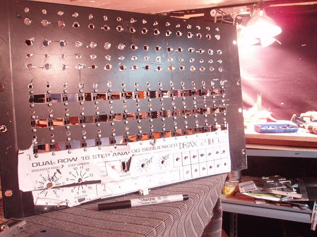
me in front of the drax unit.. its a daunting wall of shit right now.. i work on her piece by piece and hopefully it will all go fairly smooth.. i have a general idea of how it should go so. the pic of the aluminum is the armiture that holds all the boards and sub boards for the unit. this goes over top of the pots and switches in the faceplate. and sits about 1.5 inches or so away in parallel. i have to make this hinge so i can then access the pots and such when and if there will be repairs/adaptations and issues. so then the rear enclosure has a hinge and then the main board assembly will have a hinge as well. just seems like wise plan..the overlay DSVC is the extra 2 row expander module im make ing for this as well.. it extremely simple compared to the drax.. i didnt have the overlay printed i did it on the injet at home.. and seemed it and then sealed it with mylar from the art sore on both sides (3m super 77 spray adhesive wont ruin the clear overlays!!!) the next pic is the actual face plate of the DSVC on the drill press.. i work onthat as time allows as well. i make a simple black and white print out of it with all registration marks for all holes and then rubber cement that to the faceplate and puch drill from there. it gets things like 95% where they should be... ith minimal filing afterwards. so if you want to do it .. try it it that way! the last pic is the cr-8000 switches takes apart for cleaning and such.. they are super delicate and basicly what happens is the carbon comes off the top of the plunger and wont make contact to complete the circiut. so you clean it with a qtip and deoxit d5 and then shave a soft lead pencil for the lead shavings. chop it real fine and then apply it and rub it into the tiny foam pads on the plunger.. it works awesomely and pretty much indefinetely.

drax 2 continued...


well ive done some more wiring and remembered to take some pics this time. i also took some pics of the poly installed into its new home and the cr8000 switches in their undone state. theres a neat pic as well of an upcomming project...:)

Sunday, June 20, 2010

drax-2 002 taking shape


so ive been starting to wire and install all the pots and switches and do some of the preliminary wiring.. wow do i have work ahead. luckily i have a couple pics of this before they were installed and such. one is of the overlay (professionally laminated to be used industrial machine faceplates) and then some of the rear view of the armature i needed to make for all the sub modules and main boards.. this is going to be a wicked bitch to build physically. and more work than i had planned on... ill get some pics of the build as i do them.. i have one row of pots wired as of right now, and one row of leds in. . .

Sunday, June 13, 2010

the long haul

its seems this new sequencer is really taking time.. i guess it dont help tha i have several other projects on the bench as well (including a sequencer expander for it...) and a cr-8000 repair -mod and a poly six repair(extensive).. ive had to make several extra breadboard modules for it as well: 2 CMOS control line buffers, 3 led buffers, an extra gate channel, and a slide /selectable per-step portamento 4067/mux/demux control board.. so the piece ar e aaall done now and ive pretty much figured the layout of it tall behind the faceplate, and monuting etc.. have the faceplate all amachined and eady to go and have the printed overlay on the unit.(it was ridiculously hard to do with soooo many holes to align.- along with 3 rows of rectangular dpdt switches...) but it looks fairly good and should work out allright..

im projecting with everything else in life right now as well.. ill have it finished/de-bugged and running in about 1.5 -2 months... rough estimate with the current time scale. theres ALOT I STRESS ALOT of wiring to be done.. some i can really blaze trhu other shit will just eat time. so...
we'll see.

Friday, May 7, 2010

DRAX 2: revision 3.3


so i have really gone crazy. i realized while using the sequencers i have allready made that i love to use them and need more.. but being me and unhappy with they way they are .. i modiy and modify. why? cause ive always wanted to know how to do this kind of stuff. and sequencers are the only better than synths :) they are the brains that tell the arms and hands what colours and how to paint them. anyway.. so ive started this monster and figured out how to do several crucial things. 1: buffer the cmos digital control signals (allowing for longer wire runs with no defective artifacts in the controls), 2:use the cool dpdt switches that are oh so cheap (5 for a buck from allelectronics.com) and how to mount them in several style of enclosures. 3: the system for making wiring all the posts and crap much easier and faster. 4: how to build them physically so they are easier to repair or modify in the future.

so.. ive printed out a full size 300 dpi black and white copy of the face plate overlay. then rubber cemented it to the rack plate ii salvaged a while back. , then punched all the holes so as to not have the drill bit wander at all. then drilled baby. drilled. and drilled. some i couldnt do on the press since the span from the post on the press to the bit wasnt large enough any which way to fit the plate in.. so they were done the old fashioned way by hand and a power drill. anyway did every hole. for everything. alot.. then fit everything through with actual components to test fit and placement. especially all 48 of the switches. they were crucial since they have to be thru the holes so the 4/40 thread quarter inch bolts can thread into the body of the dpdt switch. i had to drill each switch hole out and re thread it to that size. they were TINY and just couldnt find the tread anywhere for them.. i imagine they were metric. but very small. so anyway i modified them and have it now..

so its all drilled. i also began making/laying/designing the armature and arrangement of the boards behind the face plate. i have 2 analog boards, one digital board, 2 led buffer boards, one gate channel board, and a cmos control line buffer board. so its not crowded but not spacious. it will be ok to wire if im careful and neat. also have been planning out how to face the boards so they are easy to remove and repair without dissambleing everything. im cutting the back fot he enclosure to have a hinged door so it will allow access without removal of a thousand screws or anything. good physical design goes along way. something i think manyfactures now forgot. they just design that shit to be throw away. fuckers.

anyway the ther projects on the bench are the cr-8000. i had to clean several of the swiches on it.. no fun. but not too bad. so i decided to mod it with trigger ins and individual outs. easy job. but i also found alot of info on the net as to how to make it into a big drum synth. im totally diggin that. so its getting a partial mod now and a big one later.

the other thing is the POLY 6 . needs the typical battery board repair. what a mess. it can live though. just needs a whole lot TLC. that guy is LUUUUUUUSH. he needs to work.

Friday, April 16, 2010

phase 3

so its all in and working: 3 channels of cv and gate. 2 of them are controlled by one brain of sorts and one by another. its ridiculous.. but the 3rd sequencer is on the way! withe the last portion (the extra gate channel) i learned to manufature the very affordable dpdt switch housings and how to do dual state leds, and single state-cycling leds as well. the extra gate channel was pretty easy to do. minus the tricky diode kluges. (which led to the possibility of the gate holds...more on that as i lay it out further. but i will do a full gate channel layout for anyone who wants to build another gate channel on theirs..its pretty damn easy and dirt dirt dirt cheap. good for env, lfo and any other sort of triggering in time with your sequence. espeically, if you have a modular.

i also inadvertantly came to 2 very nice discoveries. programmable portamento and possible gate time hold per step to give note values other than 1/6th to the sequencer!!!! the portamento is pretty much confirmed a working idea .. the gate may take some further testing. but the portamento will be implemented on the new #3 model. single housing dual channel, dual gate sequencer in a 6 U rack face with akai/emu style angled out control pad/surface at the bottom. (with walnut sides of course...)

this one has the features of the last one plus the selectable portamento. it will be smooth and refined. unlike the DRAX 2 #000 unit, which is a frankenstein and a half. but hey .. you learn on something right? its a crammed tight and almost difficult unit to work on since its grew as i worked on it.. what a freak.

anyway heres the face layout for the DRAX 2 001. for real...and also the black and white mechanical that ill use to do all the machining on the face plate..

Tuesday, March 30, 2010

small revelations


so ive been trying to figure out how to use dual state leds for the on off status /current step indicator.. i finally figured it out. u have to wire the annodes of each to either pole of the dpdt witch then run the cathode to resisted ground and then run the trigger in from the main digital board to the common. its so easy and im so stupid. this solves the dilema i had the other day..how to have the dpdt switch do trigger onn/off and show on/off staus with a light no matter if its on or off.

so. if it off lets say as the clock cycles to that step it and it hits that step it shows a red . if its on it shows a green. simple and effective.

only thing i have to do is split the trigger wire to the bottom pole of the other side and to the middle common of the the first. i may have to diode it between i think. anyway..thats that.

then the switches them selves took WAAAAAAy long to mount. i had to figure out a way to do it that doesnt involve hours of dremeling and filing. so i got 4 cutting heads for a rotary hand held grinder ($1.45 each) and then made a bolt and nut combo to lock them all between. this was then measured and used on 2 pieces of 'L' channel aluminum 3/4 inch wide on one side and 1/2 on the the other. (3/4 sides goes together) this is almost exactly the width of a 1 U rack face! perfect. so then you have a u channel about 1 and 1/2 inches accross the face with a seem splitting it in half horizontally.. now you need to put 16 rectangular holes in it. :) so you measeure (3 times before you cut) . i used metrics to do it. much easier. i went 50 mm in from the end on the left side and (almost the same on the right) and started there. i did 25 mm spacings between switch CENTERS. not from edges of them!!!! you can comfotably fit 16 in and have everything be correct then.. then after one side was completed fully i marked and did the other side.

after it all marked, you figure out how far from center line you want the switch to sit vertically. you split the differenece on either piece of aluminum. mark and number all positions and besure to double check before you start knawing this up. mount the one side you are working on in a vice!!!!!!!!!! and always wear you saftey glasses. yeah yeah i know. do it!!! STFU! your shop teacher was right so put them on you jerk. now after you have your cutter heads locked down tight, take a scrap piece and test the width of the 4 (should be almost exactly 1 switch) then secure this into your cordless drill (or corded) and then test away on the scrap. it will be slightly lopsided and bounce unless you're real good at centering the bolt inside the heds.so as i said GET THE FEEL OF YOUR TOOL> ha.

so when you feel ready ...attack you first side. grind until you hit your mark. stop. repeat 16 times. then use a file to square out and test the switch inside the hole. do the other aluminum piece. same here. file and test.

if you did it all right the holes should line up and youll have 16 rectangular openings in a 1U rack face! now you can use this alone or attach this inside another face plate for wahetever you may need! since they dont make rectangular drill bits and we dont have hand held lazers to cut yet and cnc machining is mad expensive. this is the solution i chose. im sure many others will come up with therir own! HACK AWAY!